The position of the components relative to the landings pads on the substrate deviates from the specifications.
Attention ! Always compare current standards. They are often different from each other. Here DIN EN 61191, Part 1 - 4, and IEC 61191, Part 1 - 4, respectively are taken as reference. The assessment of all solder joints is based on the standards stated above.
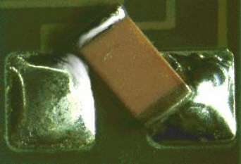
Alignment deficiencies at CMC
Description:
Clearly visible alignment fault of a CMC after wave soldering. The component has separated from the adhesive depot during the soldering process. Rework is necessary because the function is impaired. The component should be replaced. Observe soldering parameter (soldering temperature
Causes/Remedy:
- poor adhesive application
- adhesive insufficiently hardened
- poor soldering parameter
 Source:
visual, optical inspection - general view
Description:
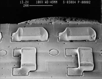
Example of end and side overhang of CMCs. The two examples on the left are acceptable and represent Class A of IEC 61191-2. The two examples on the right are nonconforming.
Causes/Remedy:
- placing faults: teaching, tolerances, systematic faults
- floating of components during reflow process
- vibration during soldering
 Source:
SEM
Description:
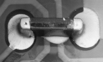
A CMC was placed with its side up. This defect does not impair function and is acceptable according to Class A of said standard. For higher requirements (Class B and C) this defect is not acceptable and has to be reworked.
Causes/Remedy:
- placing fault (incidental)
- seldom: vibration during transport of assemblies
 Source:
visual, optical inspection - general view
Description:
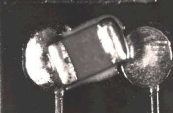
Twisting of a CMC after wave soldering; same context as described in the main file on deficiencies in component alignment. The component left its place due to insufficient adhesive force. Rework is necessary.
Causes/Remedy:
- poor adhesive application
- adhesive insufficiently hardened
- poor soldering parameter
 Source:
visual, optical inspection - general view
Alignment deficiencies at MiniMELF
Description:
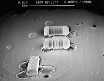
Borderline case for an end overhang of two MiniMELF. Although the overhang has not impaired the formation of the solder joint, this is to be regarded as a borderline case which is just acceptable. The minimum overlap on the right contact side must not be forgotten, however. It must not be below 2/3 (Class A,B) of the metallization width or the total metallization width respectively.
Causes/Remedy:
- placing faults: teaching, tolerances, systematic faults
- floating of components during reflow process
- vibration during soldering
 Source:
SEM
Platzierungsmängel bei PLCC
Description:
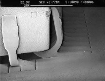
Alignment fault at a PLCC. The leads are exactly between the pads instead of on them. According to the standard the overhang must not exceed 1/2 and 1/4 of the lead width respectively. In this case rework is necessary. It is remarkable that a solder joint has formed despite the excessive overhang.
Causes/Remedy:
- placing faults: teaching, tolerances, systematic faults
 Source:
SEM
Description:
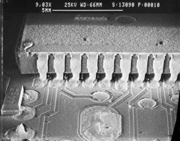
Lateral alignment fault at a PLCC. This fault is acceptable for low requirements (Class A, B) but non-conforming for high requirements (Classs C).
Causes/Remedy:
- placing faults: teaching, tolerances, systematic faults
- floating of components during reflow process
- vibration during soldering
 Source:
SEM
Alignment deficiencies at QFP
Description:
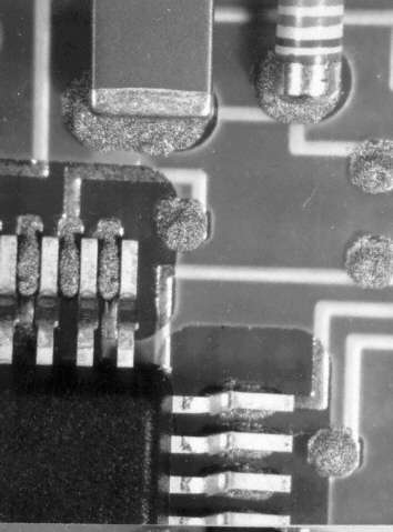
This photo was taken shortly after placing the components. On the bottom left there is a PLCC which has clearly not been aligned correctly. This can lead to defects during soldering. Here the overhang is clearly nonconforming. Rework can be done before soldering.
Causes/Remedy:
- placing faults: teaching, tolerances, systematic faults
 Source:
visual, optical inspection - general view
Alignment deficiencies at SO
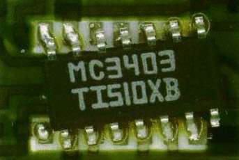
Description:
Alignment fault at a SO component. The component was twisted during placing, so that electrical connection is not possible.
Causes/Remedy:
- placing faults: teaching, tolerances, systematic faults
- floating of components during reflow process
- vibration during soldering
 Source:
visual, optical inspection - general view
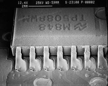
Description:
Alignment fault of a SO after reflow soldering. This overhang is non-conforming for any of the classes in accordance with IEC 61191-2.
Causes/Remedy:
- placing faults: teaching, tolerances, systematic faults
- floating of components during reflow process
- vibration during soldering
 Source:
SEM
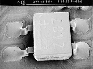
Description:
Unacceptable alignment fault. The leads on the left side overlap the pads to an unacceptably low extent. Moreover there is no solder fillet at the heels. Rework necessary in any case.
Causes/Remedy:
- placing faults: teaching, tolerances, systematic faults
- floating of components during reflow process
- vibration during soldering
 Source:
SEM
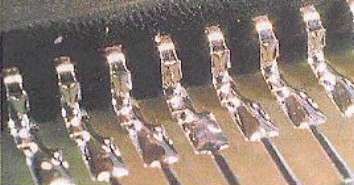
Description:
Combination of faulty alignment in both directions, lengthwise and sideways. Non-conforming. Rework necessary.
Causes/Remedy:
- placing faults: teaching, tolerances, systematic faults
- floating of components during reflow process
- vibration during soldering
 Source:
visual, optical inspection - general view
Alignment deficiencies at SOT23
Description:
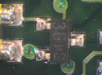
Acceptable alignment fault at a SOT23. The component has only slightly shifted. Rework is not necessary.
Causes/Remedy:
- placing faults: teaching, tolerances, systematic faults
- floating of components during reflow process
- vibration during soldering
 Source:
visual, optical inspection - general view
Description:
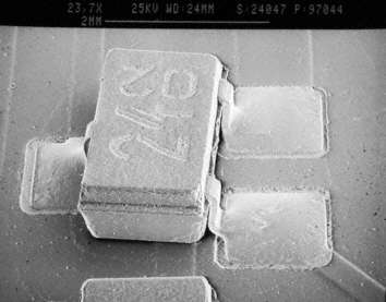
This slightly twisted component has to be reworked, since there is no correctly wetted solder fillet at the lower lead.
Causes/Remedy:
- placing faults: teaching, tolerances, systematic faults
- floating of components during reflow process
- vibration during soldering
 Source:
SEM
Description:
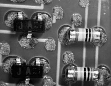
Faulty alignment of SOT23 after placing. The overhang which can cause soldering defects is clearly visible. Rework is easy in this case, as the components have not been reflow-soldered yet.
Causes/Remedy:
- placing faults: teaching, tolerances, systematic faults
- floating of components during reflow process
- vibration during soldering
 Source:
visual, optical inspection - general view
Our analytics team can help you find the cause.
go to failure analysis at TechnoLab
